
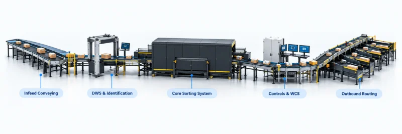


Quick answer: A parcel conveyor system layout should follow the parcel profile, origin and destination points, transfer count, required access and downstream process. Map each handoff and exception route before fixing conveyor lengths or equipment positions. A scaled site drawing with parcel samples, operating assumptions and service access gives the project team a stronger basis for a concept review than a line sketch alone.
1. Map the current parcel journey
Start by walking the process from parcel arrival to its next confirmed destination. Mark receiving, induction, scanning, sortation, recirculation, exception handling and dispatch. Record where parcels queue and where operators interact with the flow. A conveyor layout should solve a defined movement problem rather than simply connect available floor space. Identify each handoff and the system or person responsible at that point. If separate parcel classes follow different routes, mark them distinctly. The map becomes a shared baseline for operations, engineering and the integrator, and helps the team notice missing branches before detailed equipment selection begins.
2. Define the parcel profile and operating pattern
Describe the parcels expected on the line using observed dimensions, weights, packaging types and handling conditions. Include cartons, polybags, tubes, irregular items and any other form that matters to the operation. Record arrival peaks and the typical mix across a shift, not just a single daily average. Identify fragile, unstable or difficult-to-read items that may need special handling. Ask operations which profile changes are expected over the project horizon. Keep assumptions visible so the team can revisit the design if the parcel mix changes. A profile based on real samples helps reviewers assess transfer behavior, spacing, accumulation and the practicality of a proposed conveyor path.
3. Locate transfers and decision points
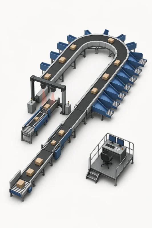
Every merge, divert, recirculation loop and manual intervention affects the path and operator workload. Mark transfer points on the drawing, then state what information triggers each decision and what happens when data is missing. Check that the physical route has a clear destination and that exceptions can be removed without blocking ordinary flow. Confirm how parcels are directed to the next area and how the operator sees a fault. A transfer that looks simple on a drawing may require a safe working zone, access platform or buffer space. Documenting the decision and the physical handoff together keeps software and material flow in the same review.
4. Plan accumulation and release logic
Accumulation protects downstream equipment from short interruptions, but its size and release logic should follow the actual process. Identify where parcels can wait, how the queue is controlled and what event releases the next parcel. Ask operations to provide examples of normal peaks and the recovery behavior they expect after a brief stop. Avoid assuming a buffer removes every upstream or downstream constraint. Check access for clearing a jam and the space required for an operator to inspect a parcel. Describe what the controls should do when the buffer is full, when a downstream destination is unavailable and when a parcel needs a manual decision.
5. Reserve access for operators and maintenance
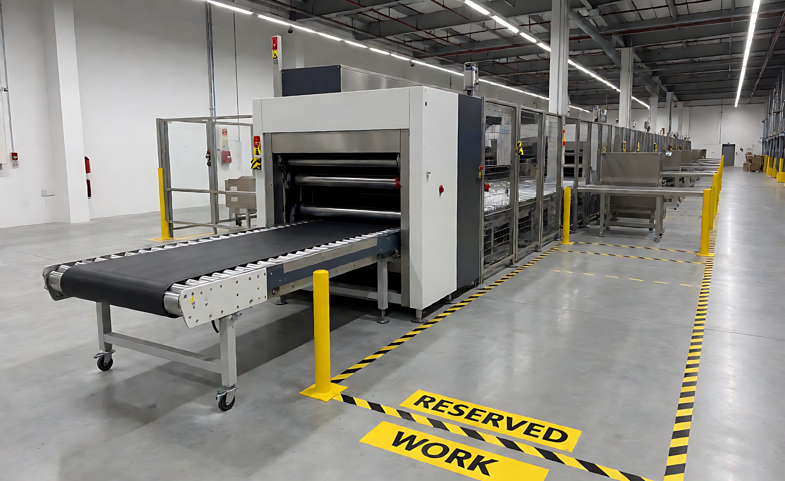
A layout needs room for routine observation, cleaning, jam recovery and component replacement. Mark walkways, control stations, maintenance access and the areas where cartons or tools are staged. Ask the site team to review overhead services, columns, doors and existing equipment that limit movement. Keep access routes visible on the concept drawing rather than relying on notes in a separate document. Include access to scanners, motors, belts, sensors and transfer points as appropriate to the chosen equipment. The maintenance team should be able to explain how a fault is inspected and how the affected section can be isolated. Practical access protects availability and makes commissioning safer.
6. Coordinate controls, scanning and data interfaces
List each equipment and software interface that affects the flow: upstream order information, scanning events, routing rules, line controls, warehouse system messages and downstream confirmation. Define what data arrives, which system owns the decision and how a response is acknowledged. Create examples for a normal read, no-read, unknown destination, duplicate event and unavailable downstream point. The exact integration requirements depend on the project, so assign an owner for each interface and agree a test record. Keep the physical layout and interface map linked by stable zone and device names. This makes later troubleshooting more precise than describing a fault only by conveyor location.

7. Use a scaled survey before concept freeze
Collect dimensions for floor area, elevations, columns, obstructions, loading doors, power, network and safety boundaries. Identify where equipment will be delivered and how it can be moved into place. Confirm the drawing revision, coordinate reference and the person who verifies each measurement. Add photographs with matching location labels. If any value is assumed, mark it and assign a verification date. Review the concept with operations, safety, IT, maintenance and the integrator before equipment positions are frozen. This survey package helps avoid late changes caused by a missed column, an inaccessible maintenance side or an interface that was not included in the original scope.
8. Define acceptance data before installation
Agree how the project will prove that the conveyor layout meets the stated operating requirement. Define the test parcel set, route scenarios, observation period, exception cases and data owner. Record throughput and queue behavior only under the agreed conditions. Include jam recovery, no-read handling, manual bypass and restart after a controlled stop. Clarify which results are informational and which are contractual. Keep open items visible with owners and evidence expected for closure. A practical acceptance plan ties the layout drawing to commissioning. It also gives operations a handover record that describes how the line is expected to behave, not just where each component was installed.
For buyers comparing available product and supplier options, see parcel conveyor system options.
Questions buyers often ask
What information is needed for a parcel conveyor concept?
Provide parcel samples and profile, arrival pattern, origin and destination map, site dimensions, interfaces, exception routes and access needs.
Should a conveyor layout include exception routes?
Yes. Map no-read, unknown destination, full buffer, unavailable chute and manual decision paths before concept freeze.
How should the site survey be documented?
Use a scaled drawing with revision, measured obstructions, utilities, access routes, labeled photos and an owner for each assumption.
When should acceptance criteria be agreed?
Agree them during design so the test parcel set, route scenarios, data owner and evidence are ready before commissioning.