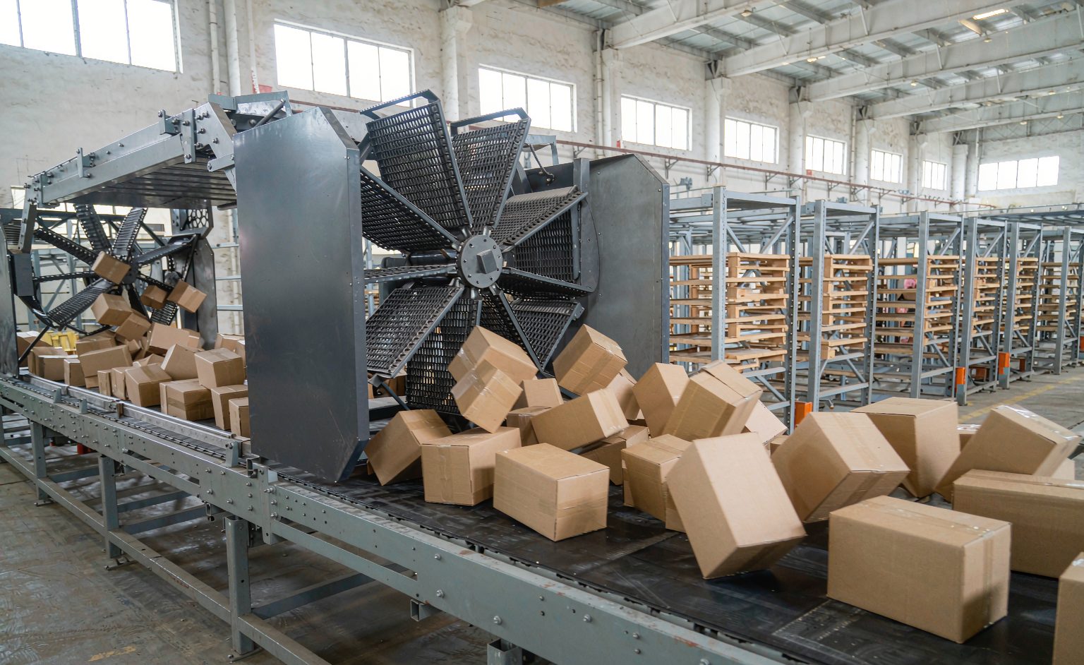
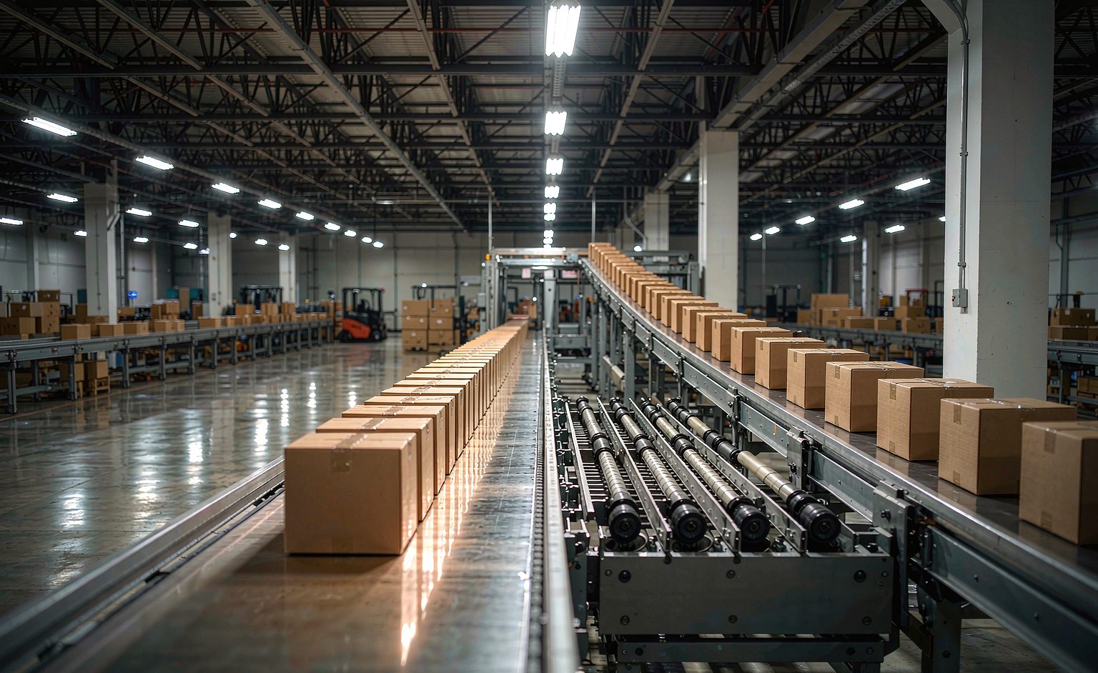
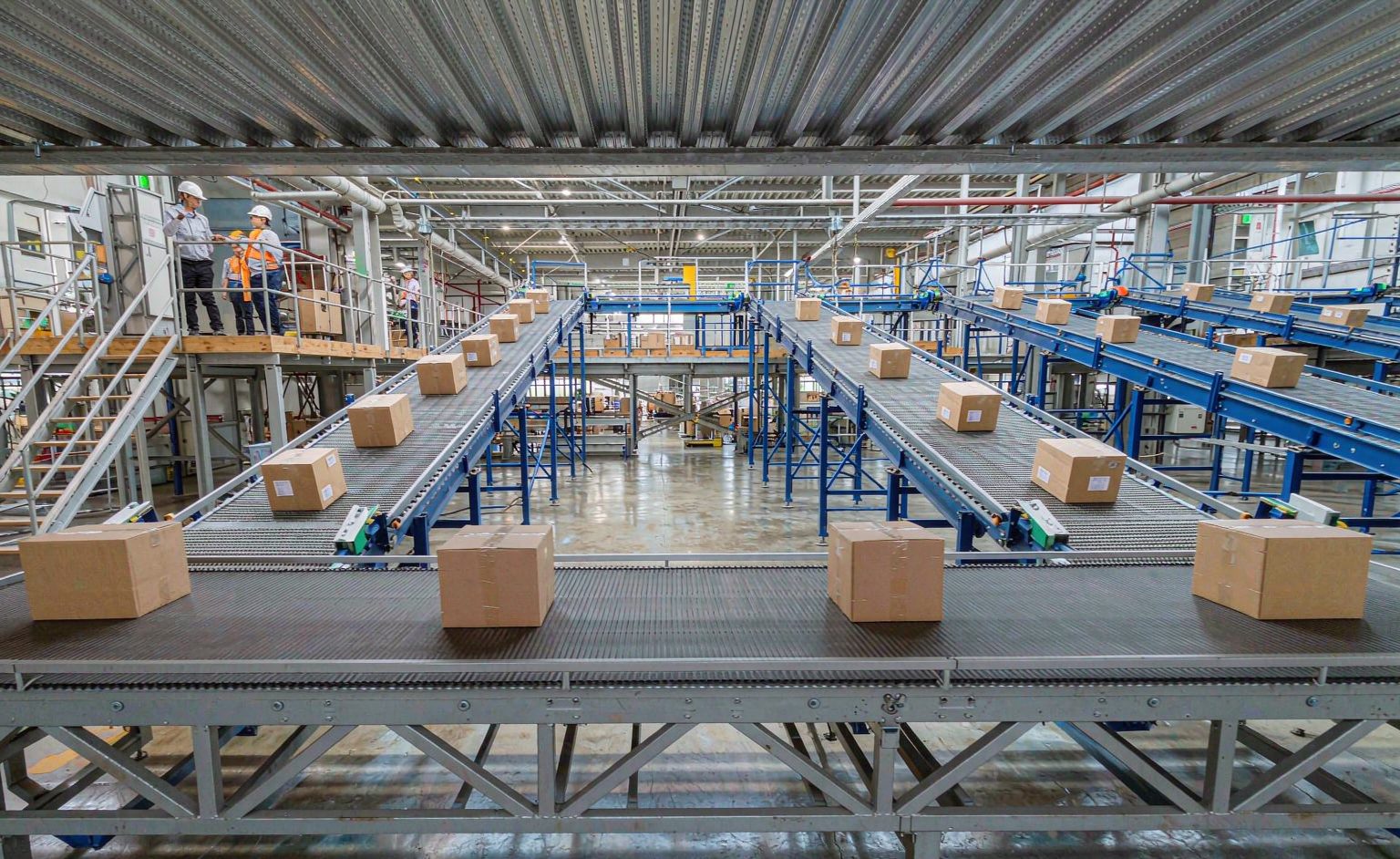
The physical layout of an automated logistics facility determines its long-term operational efficiency. Even the most advanced, high-speed sorting machinery will fail to achieve its rated performance if the surrounding material flow is poorly planned. A bottleneck in the inbound merge lanes, a cramped induction zone, or an undersized discharge area can cause the entire sorting line to halt.
Designing a high-efficiency parcel sorting system layout requires a combination of data-driven material flow analysis, mechanical engineering precision, and spatial planning. This guide serves as a practical tutorial for warehouse operations directors, facility planners, and system integrators navigating the complexities of sorting system layout design.
Section 1: Core Principles of Sorting System Layout Design
Before initiating CAD drawings, industrial engineers must establish the core principles that govern high-capacity logistics layouts. Every square meter of your facility must be optimized to ensure continuous, non-intersecting material movement.
1. Elimination of Cross-Flows and Intersections
The most critical rule in warehouse layout planning is to maintain a unidirectional material flow. Inbound packages, sorting tracks, and outbound staging lanes should move in a logical, continuous path. If your layout requires incoming raw flows to physically cross paths with sorted outbound flows, you introduce high risks of physical collisions, conveyor jams, and operational bottlenecks.
2. Spatial Zoning and Clearance Heights
Modern sorters do not exist in a spatial vacuum; they must be integrated around structural columns, building walls, electrical panels, and emergency egress corridors. Planners must map out specific functional zones:
- Induction Zone: Requires sufficient linear length for automated gapping and employee work cells.
- Sorter Track Zone: Needs adequate clearance heights, especially if designing a double-deck loop or utilizing suspended ceiling supports.
- Discharge Staging Zone: Must allow material handling equipment (forklifts, pallet jacks) to navigate safely around chutes and loading docks.
Section 2: Step-by-Step Engineering Tutorial: Designing the Layout
Follow this structured engineering sequence to design a high-efficiency automated sorting layout for your logistics facility.
Step 1: Map the Quantitative Material Flow Profile
Begin by compiling your facility’s operational data. You must determine the peak hourly parcel flow rate, the physical size distribution of your packages, and the exact number of shipping destinations (outlets). This flow mapping dictates the physical length of your conveyor lines and the number of sorting chutes required.
Step 2: Define Sorter Geometry (Loop vs. Linear)
Based on your destination count and building width, select the optimal sorter path configuration:
- Horizontal Loop Sorters: If your facility requires sorting to more than 40 destinations (e.g., individual zip codes or courier routes), a loop configuration is ideal. Loop systems allow you to place discharge chutes along both sides of an oval track, maximizing the number of destinations per square meter.
- Linear (Vertical Over-Under) Sorters: If you are designing a sorter layout for fulfillment center retrofits with narrow floor footprints, a linear over-under configuration is the preferred choice. These systems return empty carriers underneath the active sorting line, conserving warehouse width.
If your project demands a high-capacity, multi-destination setup, implementing customized cross belt sorters in a loop layout provides the mechanical stability and positive-displacement discharge needed to handle high volume spikes.

Step 3: Engineer the Outbound Chute Accumulation Metrics
An undersized chute will quickly back up, forcing the sorter control software to recirculate packages or halt the conveyor line. Planners must calculate the required physical length of each accumulation chute based on peak arrival rates and container swap times.
📐 Chute Length Accumulation Formula:
L = R × T × D × S
Where:
- L = Required physical chute length (meters)
- R = Peak parcel arrival rate to the specific chute (Parcels Per Minute – PPM)
- T = Time required for an operator to swap the outbound container/bag (minutes)
- D = Average length of a single parcel (meters)
- S = Safety safety multiplier (typically 1.2 to account for nesting and irregular stacking)
Example Calculation: If your peak courier route chute receives 12 PPM, and it takes an operator 1.5 minutes to pull a full mail bag and hang a new one, with an average parcel length of 0.4 meters:
Required Length = 12 × 1.5 × 0.4 × 1.2 = 8.64 meters
If your physical floor space cannot accommodate an 8.64-meter chute, your layout must incorporate automated chute-full sensors, dual-chute diverts, or multiple staging conveyors to prevent backups.
Step 4: Execute Upstream Conveyor Integration & Gapping
An automated sorter requires a controlled, single-file stream of packages to perform accurately. Upstream conveyor integration must include:
- Merge Tables: Combining multiple inbound feeding lanes (from unloading docks or storage racks) into a single transport line.
- Singulators: Aligning side-by-side or double-stacked packages into a single-file line.
- Dynamic Gapping Belts: Using variable-speed belts controlled by photo-eye sensors to adjust the precise physical distance between packages before they enter the sorter.
Step 5: Configure the Recirculation and Reject Loop
No matter how optimized your scanning systems are, some packages will experience scan failures (“no-reads”), missing labels, or arrive at full chutes. Your layout must include a dedicated recirculation lane that feeds these packages back into the main induction zone without interrupting the primary sorting line, alongside a dedicated manual reject chute for exception handling.
Performance Note: Sorter throughput is highly dependent on system design and integration. While automated layouts can achieve high capacities with automatic induction lines, actual performance is heavily influenced by package profiles, scan rates, and the physical flow of goods through the facility.
—
Section 3: Sorter Layout for Fulfillment Center Operations
Fulfillment centers operate under unique spatial challenges, characterized by highly diverse SKU profiles, high ratios of thin polybags, and rapid promotional spikes. When designing a sorter layout for fulfillment center environments, engineers must prioritize flexibility:
- Modular Destination Outlets: E-commerce shipping providers and postal routes change frequently. Your discharge chutes should feature modular designs that allow you to quickly sub-divide or re-route lanes without altering the primary steel track layout.
- Integrated Put-Walls: For multi-item orders, integrate your sorter directly with automated put-walls or manual order consolidation zones, minimizing the distance workers must walk to pack sorted orders.
- Multi-Level Conveyor Mezzanines: If floor space is restricted, utilize vertical warehouse space by installing your conveyor network and sorter loop on suspended mezzanines, leaving the ground floor free for picking, packing, and pallet staging.
Section 4: Common Layout Design Errors & Engineering Mitigations
The following table outlines common errors encountered during sorting system layout design, their operational impacts, and recommended engineering solutions.
| Common Design Error | Operational Impact | Engineering Mitigation Solution |
|---|---|---|
| Insufficient Induction Buffer Length | Packages back up into inbound lanes, halting upstream merges. | Design a minimum of 3 to 5 meters of metered accumulation conveyor directly upstream of each induction belt. |
| Incorrect Chute Decline Angles | Polybags stop mid-chute, or heavy cartons crash into outbound bins. | Maintain gravity chute angles between 12 and 15 degrees for rigid items. For polybags, use low-friction stainless steel or steeper angles of 18 degrees. |
| Narrow Recirculation Lanes | Recirculating packages clog the induction merges, reducing system throughput. | Ensure the recirculation lane can hold at least 15% of the sorter’s total instantaneous package capacity. |
| Neglecting Maintenance Clearance | Increased downtime during maintenance due to restricted technician access. | Design a minimum of 600mm of walk-space clearance along both sides of the sorter track and conveyor curves. |
Frequently Asked Questions
Q1: How do you calculate the optimal length of an outbound accumulation chute?
The optimal chute length is calculated using the peak parcel arrival rate per chute, the container swap time, and the average length of a parcel. The formula is: Length (m) = Peak Arrival Rate (PPM) * Swap Time (mins) * Average Parcel Length (m). For example, if a chute receives 15 PPM and a container swap takes 1.5 minutes, with an average parcel length of 0.35m, the required chute length is 7.875 meters.
Q2: What is the maximum slope angle for a gravity decline chute in parcel sorting?
For standard corrugated boxes and rigid packaging, gravity decline chutes should maintain an angle between 12 and 15 degrees. If your packaging mix contains high ratios of lightweight polybags, a slightly steeper angle of 18 to 20 degrees, or the use of low-friction stainless steel surfaces, may be required to prevent flexible packaging from stopping mid-chute.
Q3: Why is a recirculation loop critical in a parcel sorting system layout?
A recirculation loop is essential because it provides a buffer for packages that cannot be sorted on their first pass due to barcode scan failures (“no-reads”) or full destination chutes. Instead of triggering a conveyor stop, these packages continue around the track to be re-read or routed to a manual exception lane, maintaining continuous system throughput.
Q4: How does conveyor integration affect the input rate of an automated sorter?
Conveyor integration directly controls the sorting fill rate. If upstream merge conveyors do not feed parcels with consistent spacing (gapping), the sorter carriers will be underutilized, lowering the actual throughput. Upstream integration must include automated merges, singulators, and metered acceleration belts.
Plan Your Parcel Sorting Automation Project
Ready to design an optimized sorting system layout for your logistics facility? Our experienced engineering team can help you analyze your material flows, select the right carrier capacities, and design a custom warehouse layout to maximize efficiency.
TrueliSort is a manufacturer and system solution provider specializing in customized parcel sorting systems, offering factory-direct design, manufacturing, and on-site support.
Contact TrueliSort for layout planning and custom system design or email us directly at business@truelisort.com to discuss your project parameters.